Monday, 29 February 2016

Jubilee fails BSS on lack of flame trap (then passes)

Last week we went to the boat to prepare for the Boat Safety Scheme examination. This was the first time we had had to arrange one, so I didn't really know what to expect.

The examiner arrived at 1000 on Thursday and spent four hours on board. He failed the boat within seconds of starting his inspection - oh no!

The fuel tank vent, which comes up through one of the dollies, had no flame trap. I hadn't known - I didn't know what to look for. All was not lost, however, as the examiner suggested that a tea strainer could supply gauze of the right size. Unfortunately we didn't have one, having succumbed to the convenience of tea bags some years ago. But Jan was in Wolverton visiting Ally and Josiah, so she was able to buy one and bring it to me.

The brass vent cap has two circular holes a few millimeters in diameter which are supposed to hold discs of wire gauze held in place by tiny circlips. We discovered the remains of one original gauze; here it is by the vent cap. You can see one of the new gauzes and its circlip in the vent.
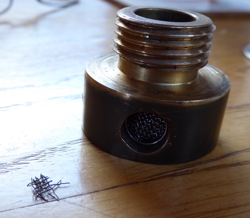
Jan had come up with four different size tea strainers; I used the one with the finest mesh (as approved by the examiner). It was quite difficult to cut, even with my side cutters.

One other item was initially failed. There seemed to be no fuse in the lead from the starter battery to the bilge pump, but I carefully followed the cable and found that it went via a circuit breaker next to the bilge pump switch on the instrument panel. Once I had pointed this out to the examiner he apologised and said that was fine, and the boat would pass. Hooray!

These days you don't get an actual certificate; like a car MOT you get a printout with the details. Only I didn't even get this; I received an e-mail for me to print out.

*************************

Back at home I gave the lawn its first cut of the year. I try to delay it as much as possible as I suspect that cutting it merely encourages it to grow more quickly. At least the grass was dry.

Tuesday, 16 February 2016

Garden scene; cold boat

Another cold morning. The sun got to work burning off the frost; this is next door's land seen from our garden.

I hope our boat's OK in this cold weather, all unlived in in the marina. I understand it's going to get milder later this week (phew!); meanwhile I expect there's a certain amount of ice breaking being done by any boats on the move.

Ally visited the boat briefly today in order to close the internal door between the engine room and the rest of the boat. I had forgotten to shut it when leaving a week ago; with it open there's not much protection from icy blasts around the back doors (and coming through the vents). We have a thermostatically controlled fan heater in the cabin, set to minimum, but there's no point heating the outside.

Thursday, 11 February 2016

Forced ventilation for the fridge

On the boat the other day I made a bit more progress in my quest to make the fridge more efficient. I had already cut a hole in the floor under the fridge's radiator; and cut a ventilation grill in the panel immediately behind the fridge. Now I have added a small 12V fan in an attempt to blow the warm air from the radiator.

At the moment this relies on me connecting the fan to 12V and switching it on and off manually. A quick look at the back of the fridge shows me that a direct connection to sense when the compressor cuts in won't be easy, so I'm considering either a noise sensor or a heat sensor to tell the fan to come on.

The fridge is by far the biggest drain on our domestic batteries. If this doesn't work I might have to spend a small fortune on buying a 12V fridge, surely more efficient than running the 3kVA inverter and the mains fridge.

Saturday, 30 January 2016

Jubilee gets a new alternator (and a diesel top-up)

By way of a break from relentless alternator argy-bargy here's a shot from this morning as the Jules Fuels boat prepares to untie and call on us, as arranged, to sell us some diesel. I like to keep topped up during the cold weather in order to minimise the amount of condensation in the tank.

So, back to the alternator. Yesterday afternoon, as a result of a conversation Jan had on Facebook, Tim Casentieri turned up with a brand new alternator for me! I had paid over the phone while Tim had been at Electrostart in Daventry; then he and his wife, Roberta, drove over to see us and help me install it.

Well, Tim actually did the installing; Jan supplied coffee and I passed over various tools as required. Tim preserved the "bolt-on" regulator as per the original setup. When I started the engine my current meter didn't show a big increase in the charging current over what it had been when running on the engine alternator alone. I put that down to the fact that the batteries were already well charged. Time was getting on, so Tim and Roberta left and I continued to think about the Sterling ABC and whether that was helping or hindering. I still don't really know.

There is at least one good thing the Sterling device does, which is to limit the charging voltage to 14.4V to keep the sealed lead-acid batteries happy.

Here is a poor photo of the back of the new alternator, taken after I'd replaced all the deck boards and just before we drove home (oops!)

This morning I disconnected the Transpo regulator and started the engine. It seemed to work as before (but the feed to the "L" terminal was taken from the engine battery side of things - not how it should be). As a better test of the alternator's capability I switched on the inverter and plugged in a 800W toaster. I was pleased to hear the engine note drop; when I consulted the current meter I saw it reading about 33A. Good. (The inverter supply doesn't go through the current meter's shunt, so the reading doesn't reflect the power consumed/supplied.)

Then I reconnected the Transpo and performed the same test. Same result. The alternator stayed gratifyingly cool throughout. After lunch I winded Jubilee and we returned to Thrupp Wharf Marina. During the journey I noted that the battery voltage stayed at 14.3V the whole time. I seem to remember that, in the past, the voltage would sometimes be 14.4V and sometimes 13.7V. This, presumably, was when alternators and Sterling ABC were all working properly. Now I am really suspicious of the ABC, but don't know how to test it.

Dave Ward's advice to me is to ditch it altogether, separating the two charging systems (engine alternator/battery and domestic alternator/battery bank). I am inclined to think that might be the best thing to do, but I have some time to consider the options before returning to the boat.

Friday, 29 January 2016

Alternator update

Many thanks to all who have commented with suggestions and sympathy (that's how I'm reading yours, Jim!). Dave Ward has gone out of his way to help - thanks Dave.

I have spoken to Ed Shiers of Four Counties Marine Services who would come and fit a new alternator for £360. Dave Ward has found a potential replacement for £182.40. I have contacted West Lancs Auto Electrics who have quoted £145 including delivery, but when I mentioned the external black box thingy they were surprised, saying that the Sterling ABC should look after the regulation. I don't know why an external regulator has been added, as I understood alternators to have internal regulators, as a rule.

So ... £360 for someone who (presumably) knows what he is doing to come and sort things out ...

Or £182 for a Prestolite equivalent alternator which I could pick up from home ...

Or £145 for a like-for-like Prestolite from West Lancs to be delivered.

I have an idea what I'm going to do, but I'll let you all have your say if you like (and I think I know what you're going to say!)

Here are some more photos, starting with the space where the alternator goes.

This bolt goes through the mounting holes, securing it to the black cylindrical protrusion from the engine foot.

Here is the alternator with its external black box.

This is the label ...

... on the black box ...

... and this is the other side of the black box. The wires disappear into a slightly squishy rubbery compound.

I will let you know what happens next!

Tuesday, 26 January 2016

Alternator gets very hot

Yesterday we brought the boat down to The Galleon in order to be closer to Ally, Ben and Josiah. When I tied up I noticed a strange smell coming from the engine hole - a hot sort of smell, but not hot oil. The domestic alternator felt especially hot; it was also making a new noise. I don't think it has been charging the batteries very well, despite the voltage being between 13.8V and 14.4V when the engine was running. The batteries quickly went down to 12.7V even with no inverter load (inverter switched off).

This morning I investigated the digital ammeter I bought from Amazon a short while ago - the display unit is definitely faulty. I checked the voltage across the shunt with my DVM and obtained sensible readings. Incidentally, connecting or disconnecting the inverter negative lead from the battery bank made no difference, so all the charging current is via the shunt; so is all the discharging current apart from the inverter.

I connected my centre-zero moving coil voltmeter across the shunt to allow me to monitor the charging. The scale is marked 10 - 0 - 10 (volts). Full scale deflection would correspond to 114A; with this in mind I was interested to see that, when I fired up the engine again from cold, the charge current measured just 5A. Within seconds the alternator body was almost too hot to touch; the internal fan was blasting out hot air and that strange smell. Cooking enamel insulation?

Other relevant facts: the outputs of the engine and domestic alternators are combined in a Sterling Alternator to Battery Charge Controller stuck to the steel wall of the engine room. When we got to the boat on Sunday the engine room was thick with condensation - all over the engine, the walls and the Sterling ABC. Had this water got inside the device and affected it? When I checked the ABC before switching the engine off after the run yesterday I saw a warning LED glowing, corresponding to "HIGH ALT TEMP, STOP". (There are temperature sensors on each alternator and one of the batteries.) If nothing else, this shows that the temperature sensor on the domestic alternator works, and that the ABC is recognising this. Everything else on the ABC seemed to be working normally.

What I would really like to know is ...
  1. Is there an easy test to see if the alternator is working properly?
     
  2. Is there an easy test to see if the Sterling ABC is working properly?
     
  3. If the Sterling ABC is faulty is this what has caused the demise of the alternator?
     
  4. Is the alternator definitely dead?
     
  5. Is there an easy way to bypass the Sterling ABC?
Here are two more views of the alternator.


The alternator appears to be a Prestolite AVI128 110A.

Sunday, 24 January 2016

Proud grandparents

Early this morning our daughter Ally gave birth to a son, Josiah, weighing 6lb 14oz (or 3.13kg if you prefer). We drove over to MK to have a look for ourselves ... and here he is at just ten minutes old!

No, we didn't get there that quickly - Ben sent us the photo. Here are a couple I took this afternoon with the very proud parents Ally and Ben.


Josiah is our first grandchild, making us proud grandparents (and making me feel quite old!)

I like the canal connection. Josiah Wedgwood was one of the instigators of the Trent and Mersey Canal, which opened in 1777 and greatly benefited his pottery business. (The "original" Josiah was a king of Judah, acceding the throne at the age of eight. "He did what was right in the eyes of the Lord and followed completely the ways of his father David, not turning aside to the right or to the left." (2 Kings 22:2))

Wednesday, 6 January 2016

Ammeter wiring - why doesn't it work?

I promised to show you how I connected my 100A ammeter. Perhaps someone might be able to point out why it doesn't appear to work. Please excuse the scrappy (and dark) nature of this wiring diagram:

The current shunt is in the negative path immediately before the battery bank (four 12V batteries in parallel, not four cells in series!). The actual negative cables attached to the non-battery side of the shunt are one to the engine block "earth" and one to the domestic negative busbar next to the circuit breakers.

The thin wires to the display unit are connected to battery + and either side of the shunt.

On my diagram I added the connections to the inverter as an afterthought. Having done so I am now wondering whether the negative cable to the inverter could actually be earthed there, thus bypassing the shunt.

Whatever, the result of this wiring is that the boat electrics function normally but the current shown on the display unit never exceeds 0.4A, whichever way round I connect the thin wires to the shunt.

Any ideas, anyone?